Author’s note – For clarification purposes, SOLIDWORKS will be referred to as ‘SOLIDWORKS CAD’ to differentiate from SOLIDWORKS PCB.
Though STEP files are critical in collaboration between MCAD, such as SOLIDWORKS CAD, and ECAD, such as SOLIDWORKS PCB, an important issue has become more significant as of late. Because there are many ways for an electronics designer to obtain STEP files, it is difficult (if not impossible) to know what tool was used, or more importantly if the STEP file was validated. This is not just true for components that may have been downloaded from 3DContentCentral.com. Also, such components can be provided by OEMs who then, provide them to suppliers, such as Digi-Key and Mouser.
Why is this now an issue? In the first generation of MCAD / ECAD collaboration capabilities, a STEP files pulled into an MCAD tool were broken into their elementary sketches. Now, with SOLIDWORKS PCB directly collaborating with SOLIDWORKS CAD, the STEP is no longer a collection of sketches. It is brought into SOLIDWORKS CAD as a single part. Unlike SOLIDWORKS PCB, SOLIDWORKS CAD expects that the STEP file was drawn correctly.
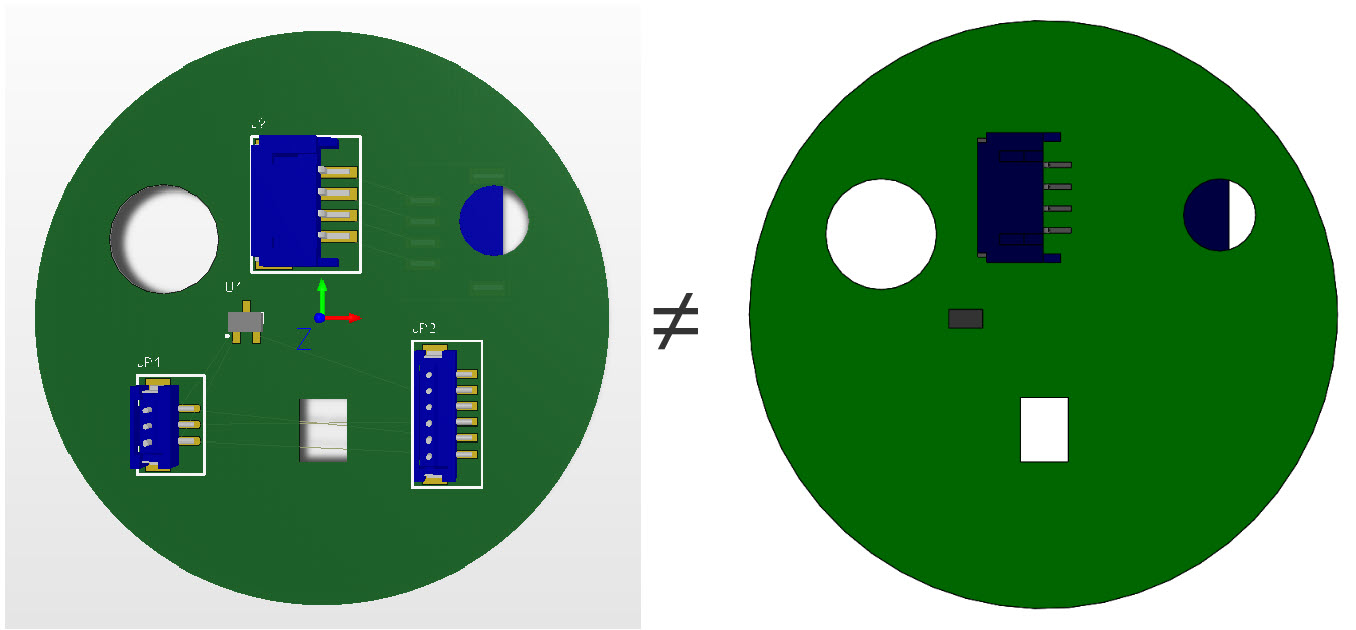
What was acceptable in SOLIDWORKS PCB (left) may not be acceptable in SOLIDWORKS CAD (right) if there are any issues found in the component’s STEP representation. Notice how several components are missing from the SOLIDWORKS CAD’s rendering of the PCB.
SOLIDWORKS PCB is more forgiving; it has no need for the interrogation of the relationships between sketches of a given component’s STEP. The purpose of the STEP file is for physical clearance rule checking and 3D visual representation.
The collaboration between SOLIDWORKS PCB and SOLIDWORKS CAD may start in SOLIDWORKS CAD, but the electrical components must be declared in SOLIDWORKS PCB. In electrical design, there are two component representations. The first representation is symbolic, used in a schematic drawing which is dimensionless. The second representation is the footprint, used in the physical layout of the board.
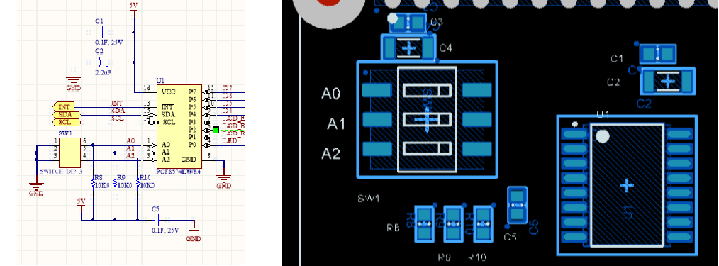
In SOLIDWORKS PCB, each component is represented by two graphics, the schematic symbol, and the PCB footprint.
In the past, the footprint was simply that – the pads to which the component would attach during the assembly process. However, the 3D representation is now added, allowing additional physical clearance rule checking (as well as aesthetics). With collaboration between SOLIDWORKS PCB and SOLIDWORKS CAD, it is simply a matter of bringing work done by the electronics designer to the mechanical tool for fitment and placement assistance.
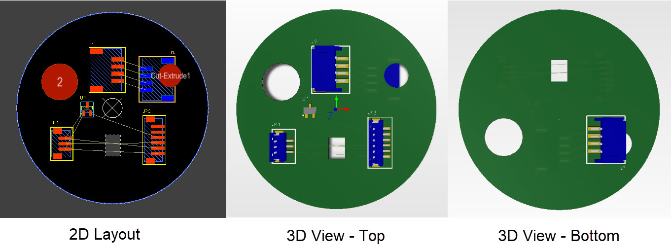
Though most of the layout work in SOLIDWORKS PCB is performed in the 2D view, the ability to add STEP representations to the footprints allows the designer to view the board in 3D and directly collaborate with SOLIDWORKS CAD.
If the 3D representation of the component is first introduced in SOLIDWORKS CAD, it has no relationship to any components in SOLIDWORKS PCB. Unfortunately, it is not a simple matter of linking the 3D representation to an existing footprint in SOLIDWORKS PCB. It must be embedded in the library. Thus, it is easier for the electronic designer to create the symbol, the footprint, and include the STEP model in the footprint when making the component in SOLIDWORKS PCB.
Since the electronics designer needs to create the library, they are always looking for available STEP files, as most do not have the ability to draw their own. Therefore a procedure is needed so the STEP file can be tested and repaired prior to being added to the library. Repairing the STEP file after it has been used in a PCB layout becomes a messy process.
In a future article, we will discuss ways of correcting components with STEP files that cause MCAD errors. For now, the recommendations are:
- Obtain models from those individuals and organizations who are well versed in SOLIDWORKS CAD.
- Open STEP models obtained from outside sources in SOLIDWORKS CAD. Make sure that the tool does not flag it for errors. SOLIDWORKS CAD has analysis tools that with little assistance can repair most errors.