In the field of printed circuit board design, there has been a constant clamor to get designers off the imperial unit system known as the mil. The mil is 1/1000th of an inch. It has been used throughout the history of PCB design. Classic component packages like the DIP were designed using the mil for pin spacing.
The “preferred” recommendation is the use of metric system’s millimeters (mm) in a perceived need to be integral in the global economy. But there is an issue that makes the transition to millimeters anything but smooth. Mils and millimeters mix like oil and water. The conversation between mils and mm is not along with some convenient multiple of five, ten, or any integer. 1 mil is 0.0254 mm.
In the video Who Invented the Meter? On the “It’s Okay to Be Smart” channel on YouTube, the unfortunate conclusion is that the meter is nothing more than an arbitrary length of metal. The creation of the meter was set out to be a measurement that was in line with the universe. It was based on measurements taken on the Earth’s surface in a time when humans had not yet flown, launched a satellite, or had any laser or electrical gadget to obtain readings accurately. More so, it assumed that Earth was perfectly round. This is not the case, given the bulge at the equator. Therefore, the metric system does not have any solid scientific foundation to justify it over the imperial measurement system.
From a practical perspective, the metric system does not have a good intuitive range for printed circuit boards. A “good intuitive range” for an item is where the unit of measure does not require one to think in fractions or large numbers. Measurement should be intuitive, allowing the human mind to associate the numbers to the item being measured quickly. These numbers should give relative meaning to the concepts of what is bigger or smaller.
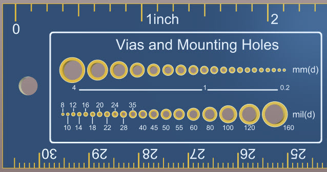
In print circuit board design, 40 mils (~1 mm) is a large number. To give some idea of relative size, all fabricators can produce traces of 8 mils (~0.2032mm) with 8 mil spacing. Many fabricators can go to 4 mils (~0.1016 mm) of trace and space. From the numbers listed, what’s easier to mentally process, a 4 mil trace or a 0.1016 mm trace? Granted, you can get by rounding so that for every 4 mils, you have approximately 0.1 mm. Why work in fractions or approximate units of 4?
The next metric unit that could be considered is the metric system’s Micrometer (aka Micron), of which 1000 um is 1 mm. The problem with this measure in printed circuit boards is that it is too granular, resulting in more significant numbers. 5 mils become 127 um.
You may also argue that most component packages are designed in millimeters. That is fine. Any decent EDA footprint editor has properties and/or wizards allowing the user to enter the values in either unit. In the end, these components are placed on the boards where rules drive the creation. Is it easier to deal with a 10 mil clearance or .254 mm clearance? Is it easier to size the width of a trace to 7 mils or 0.1778 mm? Is it easier to size a via with a 12 mil hole or a .3048 mm hole?
The obsession with making the EDA tools metric has even spilled over to the schematic editors. Unlike the PCB editor, where actual dimensions are required, this is not the case in the schematics. Schematics, by their nature, are conceptual and dimensionless. They are not in any way supposed to be drawn to indicate scale or size. Before Altium Designer version 18, its default measurement in the schematic and schematic library editors used was called the DXP unit, based on a 10X multiple of the mil. It enforced the idea that the schematic and its symbols had no dimension. As for the use of mils in the schematic editor, the drawing area requires a coordinate system. Like printed circuit boards, the mil seems optimal for these editors. Why? Because displays work in DPI (Dots Per Inch.)
In conclusion, you can rack your brain working in the metric system because you wish to conform and appease some bureaucrat. In the end, it does not matter because it can all be converted into units that the fabricator and assembler need to complete your board. When we communicate with each other on design-related matters, it is in mils. When we train, it is in mils. Though IPC spec shows both mils and millimeters, it is apparent by the numbers that many tolerances and lengths are based on the mil. Therefore, when it comes to printed circuit board design, I will stick with mils; thank you very much.