- Mental Amusement
- The aXe Files
- The Rust of Yesteryear
Mechanical Layers Revisited
Several years ago, we decided to put out a list of recommended mechanical layers for Altium Designer (Click Here). Altium Designer is different from other tools in that Altium does not predefine its mechanical layers. In tools such as Cadence Allegro, mechanical layers are very well defined. They are so numerous. It makes finding things in Allegro a bit more challenging.
Altium Designer provides mechanical layers and allows the user or company to define the layer. In Altium Designer 18, Altium has introduced 'layer types' so that there can be some mapping of commonly used mechanical layers such as assembly, courtyard, and 3D bodies that may have been allocated to different layers between the PCB layout (.PCBDoc) and library files (.PCBLib). Though this is certainly useful for those consultants and services that must work between their internal practices and customer needs, this can only be looked upon as a quick fix for a given project and will still require some effort to ensure that all mechanical layers are correctly represented when there are differences between two or more PCB files.
Though Altium does not have an official list of recommended layers, their implicit recommendations are built into their libraries. For example, the libraries Altium and Octopart (owned by Altium) have the same layers for 3D bodies, assembly, and courtyards. Knowing this can make footprint creation easier if one starts from these libraries. It is to note that Nine Dot Connects generally does not recommend starting with a 3rd party library, given that there is no assurance or guarantee that the part has been correctly designed and vetted. The time it takes to review and ensure that the imported library footprint is valid is about the same time necessary to create the footprint from scratch.
In 2017, we released our recommended mechanical layer list. This list came from a large project we assisted for a company that was pulling together all their designs (about 50) scattered about in various hard drives due to mergers and acquisitions. Some of the designs had been designed with other tools. Some of the designs only had Gerber files. Some of the designs only had PDFs of the schematics. To bring commonality to what we were trying to clean up, the mechanical layer list, which we call 'Rev 1', was created. It is important to note that we still stand by this list and that those who may have adapted it are not missing out. It is more comprehensive than the 'Rev 2' list.
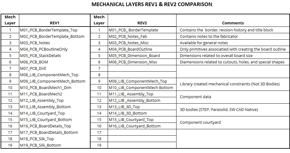
The 'Rev 2' list addresses changes in Altium Designer's offerings and better organizes mechanical layers. With Draftsman's recent addition, we removed the bill of material, drill, and stackup from the mechanical layer list. These are best handled in the Draftsman tool. We also removed the silk layer top and bottom. This particular mechanical layer aimed to allow additional information to be written without actually placing it on the dedicated silk layers. However, this information can be readily added to the mechanical layer dedicated to notes.
In 'Rev 1', two layers were dedicated to 3D bodies added to the layout that had no association with any components. However, since mechanical layers associated with 3D bodies are not used in manufacturing documentation, these additional 3D bodies can be readily placed on mechanical layers dedicated to 3D bodies.
'Rev 2' lists a border template for both the top and the bottom. There is no need for a bottom template, given that the print options will allow the top template to be used for viewing mirrored layers if desired.
In addition to removing several layers, the revision two lists organize the layers based on their primary usage. Layers one through six are specific to the layout. Mechanical layers seven and eight were left blank to allow for additional PCB-related layers if the individual or the company saw a need to use them.
Mechanical layers 11 through 16 (3D bodies, assembly, courtyards) match with both Altium’s provided libraries and Octopart.
Also, we allocated mechanical layers 9 and 10 for mechanical constraints that are not specifically related to the 3D bodies. These could be notes or dimensions to assist with understanding any complexities that the component may bring about. (Note that the dimension primitives in Altium designer are not available in the PCB library. However, dimension information can be drawn using the line and text primitives available.)
One word of caution... Octopart has made use of mechanical layer 10 for a component package outline. This outline is not a courtyard. It simply outlines the physical package minus any pins that may extrude from it. We at Nine Dot Connects are not sure why this has been provided. Unfortunately, it also does not adhere to the use of an odd number to begin mechanical layer types representing both the top and the bottom. There is no need for it (as far as we know), and feel free to remove it if you wish to use the list we have provided.
That brings us to our last point. This list is simply a recommendation. There may be things that you or your company needs that are not included. Mechanical layers for glue dots, plating, etc., can be added or moved at one's discretion. In Altium Designer 20, there are now over 1000 mechanical layers available. Keep in mind that the more introduced layers, the more effort it will take to design a new footprint.
