Legacy Data

The purpose of this commentary is to better understand the consequences of moving data from one system to another. This commentary is primarily focused on printed circuit board (PCB) projects and component libraries; however, this can be applied to other industries where top-level files reference other foundational documents.
Some terms need to be defined:
PCB Project - This is a drawing package consisting of one or more schematics, a PCB layout, and documents generated to assist and instruct in the fabrication and assembly of the PCB design.
Schematic - An electrical drawing that is conceptual in nature, meaning that it is dimensionless. Components are represented symbolically. The connectivity between the components (known as a netlist) is provided to the PCB layout drawing to assist in the copper routing of the board.
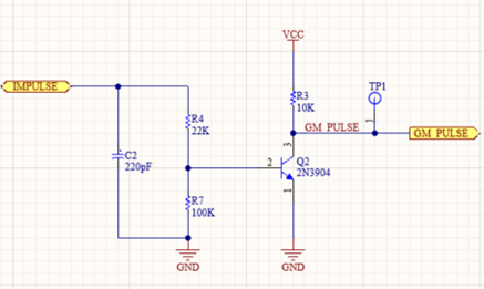
Figure 1 - Example of a Schematic
PCB Layout - A drawing of the physical layout of the board. This not only includes copper routes between components but also provides the solder points for the components to the board, known as footprints.
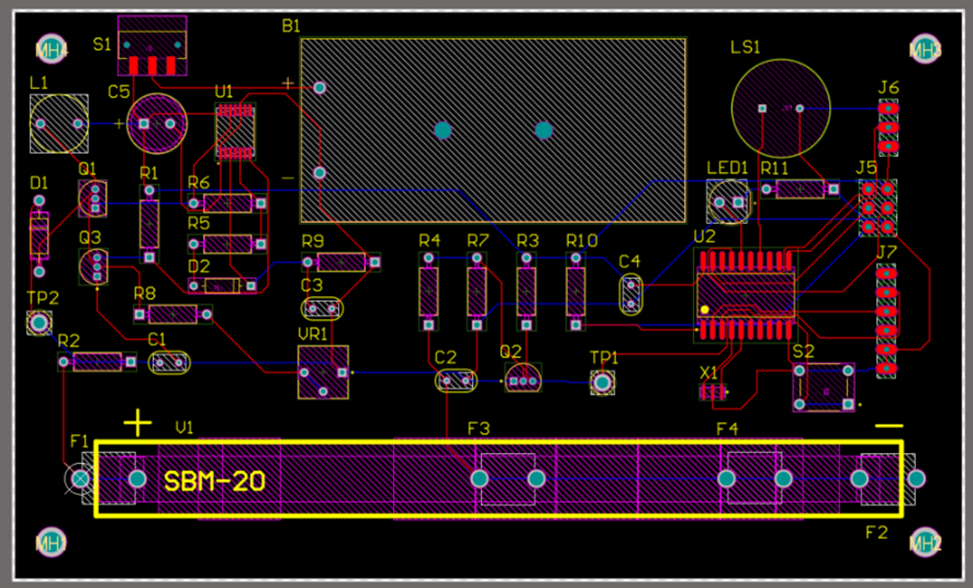
Figure 2 - Example of a PCB
Component - An electronic device that is placed on a circuit board to provide functionality. This could be a resistor, capacitor, connector, processor, etc. For a component to be of use to a PCB project, it must contain parametric data such as name, part number, description, etc., that allows the designer to search for it in a library and to list it in a bill of materials. Each component must also contain a symbol for representation in a schematic and a footprint for representation in the PCB layout.
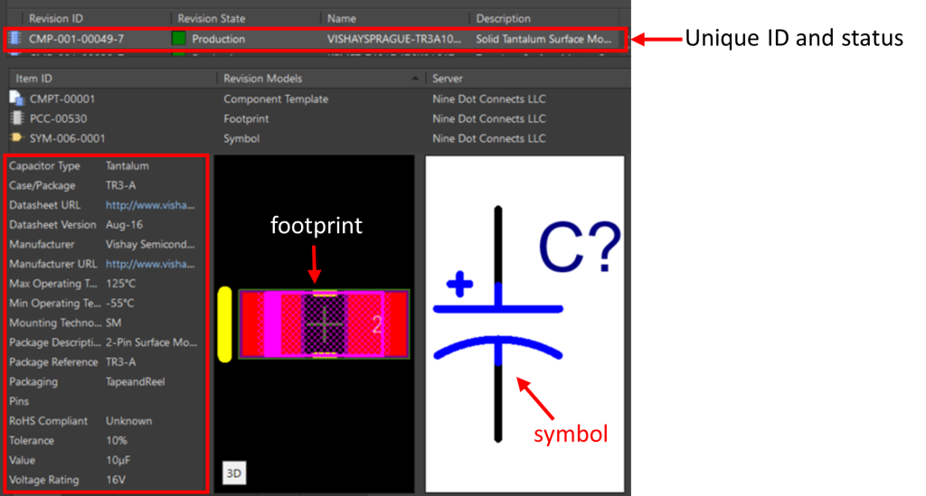
Figure 3 - Example of a Component
Component Library - A collection of components. Though there are different library structures, for the purpose of this document, we will refer to a "component-centric" library. This is a library in which each component is defined by three files: A component file containing the parametric data, a symbol graphic file, and a footprint graphic file. (Database libraries also fall into this category, with the exception that the component is defined in a table of the database rather than a separate file.)
Legacy - An existing (and usually completed) project or library file that is being brought into a new documentation system.
Before we can jump into legacy issues, one must understand how a PCB project comes together. If you are familiar with PCB design, you may skip this section.
All PCB projects start with the schematics. In the schematic editor, the designer must place components from their component library onto the schematic. Most PCB design tools do not allow the user to create the component within the schematic editor. Even if they did, this is not a good design workflow practice.
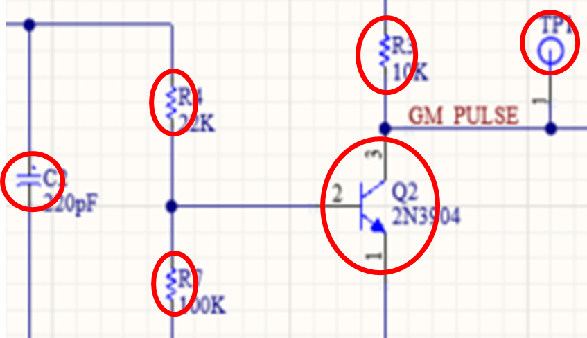
Figure 4 - Components in a Schematic
If a component is required and is not in the library, the designer must create the component in the library tools and then add it to the component library. As mentioned in the definitions above, this consists of defining the component and providing it with a symbol graphic for the schematic(s) and a footprint graphic for the PCB layout. From there, the designer can place the component's symbol. (The footprint will be introduced to the layout after the schematic is complete.)
With rare exception to design tools dating back 30+ years, all design tools use a static library placement method. A static library placement means that upon placing a component from the library, information about the component and its symbol is copied to the schematic. This is important for several reasons:
- If changes are made to the library, they do not automatically propagate to the schematic. Though this might sound like a good idea, there is a good possibility that someone will change the component in the library after the completion of the design, thus modifying the design long after the design was completed without the designer's knowledge.
- If the project files containing the symbols are sent to another person who does not have access to the library, they can still open the project in the same design tool and see the complete schematic.
- This concept also applies to the footprints placed in the PCB layout.
The static library placement method will play a role in dealing with legacy issues, which will become more apparent later.
Once the schematic is complete, the connectivity information, along with the component information, is provided to the layout tool. Since the design tool already knows about the component, it will automatically retrieve all the footprints. Since the connectivity information has been provided, lines (referred to as the rat's nest) will be provided to allow the designer to place the components strategically and to follow these lines when routing.
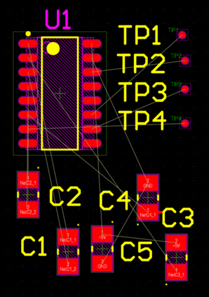
Figure 5 - PCB Footprints with Interconnectivity (Rat's Nest)
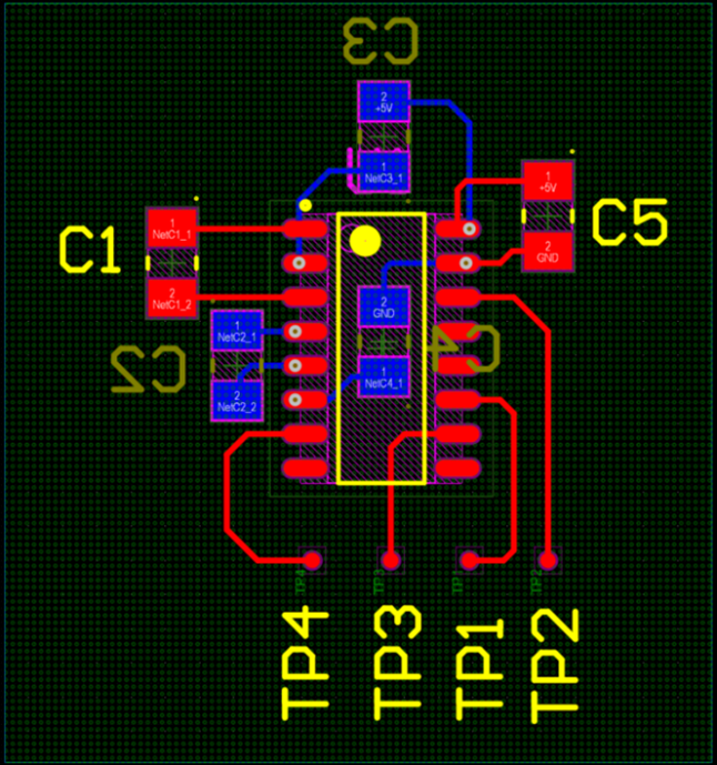
Figure 6 - Completed Layout
Once the layout is completed, documentation will be generated for the manufacturing of the board. As a good business design practice, a copy of the project is then uploaded into a company system (usually a PLM) for safekeeping of the revision of that board.
As for the original copy of the project, it is generally left in the directory where the individual started it. It may have also been saved to a local repository as well, though one cannot work in the local repository, so it must be checked out to a local directory.
-------------
When the project is complete, one has a copy of the project and a library of components. Traditionally, the component library and projects have been kept separate. However, there are tools such as Altium365 and Enovia 3DX that allow the company to keep both the projects and the libraries together. When there is a desire to maintain the relationship between the components and the projects when moving to a new documentation system, maintaining the relationship between the two becomes an endeavor.
There are three fundamental questions that need to be considered:
- What to do with the existing libraries?
- What to do with the existing projects?
- What to do with the components in the existing projects?
Before addressing each one of these questions, it is important to recognize that all documentation systems are databases. By their nature, all database systems have a unique identifier assigned to each file. The only way to preserve this unique ID from one system to another is in situations where the backup of the source system can be restored to the destination system. In fact, this is commonly done for companies that are moving from Altium's Concord Pro to Altium A365. But it also should be noted that this is an "all or nothing" procedure. Data that was already on the destination server is going to be overwritten during the restoration process.
If one is moving between different systems or gathering files into a new system, this is generally referred to as "migration." In this process, a new unique ID is assigned to each file. Any prior ID is not salvaged and reused. The ramifications of this will become clearer when dealing with components that exist in projects.
What to do with the libraries?
It is rare to simply take an existing library and migrate it to a new documentation system. In most cases, the libraries are not consistent in their appearance nor necessarily complete in their graphical and parametric data. Prior to migration into the new system, it is not uncommon to edit components and modify their graphics to gain consistency. Since the destination system is revision-based, such changes are better edited and modified externally prior to the migration of components into the system.
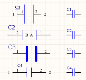
Figure 7 - Examples of Inconsistent Capacitor Symbols Replaced with Consistent Ones
If the libraries are modified and then migrated into the new system, they are not only different from their prior library, but they are also different from the components that were used in the projects. Recall that the project files contain components via "static placement." The library components that were migrated into the documentation system are not automatically propagated to any projects.
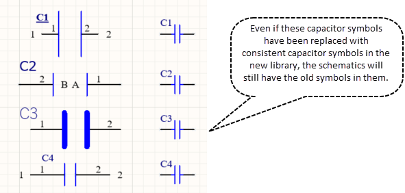
Figure 8: Example of Schematic with Inconsistent Capacitor Symbols
Some companies may opt to simply leave the libraries "as is", migrate them, and then modify components as needed later. In such cases, these libraries should be marked with the lifecycle status as being "legacy." The recommendation is that any component of interest in a future design should be reviewed. If changes are made (which is highly likely) to the component, the system will save it as a new revision, and its life cycle should indicate that it is approved for use.
What to do with the projects?
The second aspect is the migration of the projects into the system. Unlike libraries, completed projects should NOT be modified prior to or after the migration into a system. It must be assumed that a prior project is complete and that any changes to the project should be considered a revision change. These projects should also be marked as "legacy" to indicate that they were not created with components of the current document system. If a project needs to be revised, by the nature of the documentation system, the changes will invoke a new revision.
What to do with the components in the (legacy) projects?
One of the benefits of using a documentation system that maintains both the component library and the project files is that a component can be tracked to various projects. By doing so, the user can be immediately informed if a new revision of the component has been released. It also allows for a bill of material tracking as well.
Recall that a project contains components that were copied from the library at the moment of placement (a.k.a. static placement.) If they came from another file management system, the unique IDs would not match. In addition, it is highly likely that the symbol and footprint graphics were changed if the libraries were heavily edited (a.k.a. library restoration) prior to migration and/or if the migration required the conversion of library structures.
If there is a desire to have the project sync with the libraries in the file management system, each component will have to be swapped with its corresponding library component. Simply put, the old component residing in the project is deleted, and its corresponding part from the new documentation system is placed. Granted, there are tools that can do this automatically; however, doing so would likely be detrimental to the design. Three reasons why:
- There can be graphical changes to the symbol pins, such as initial orientation, pin length, pin location, and the offset from the origin. This will be reflected in the schematic upon placement.
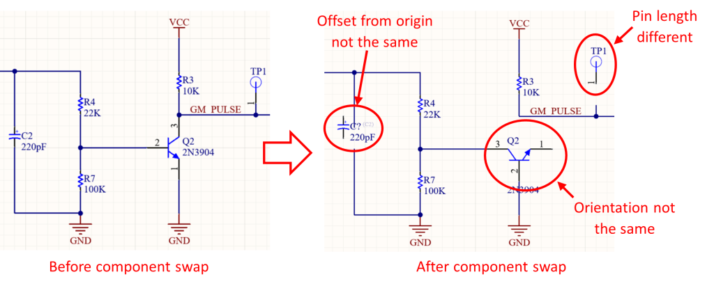
- Blind replacement from an automated tool can break connections and/or create false connections.
- Similar is true for the graphics pertaining to the footprint, such as pad size, pad pitch, mechanical layer, and silk changes.
- The designer of the project may have modified the symbol or footprint. Though one cannot create a new component in the schematic or PCB editors, one can modify the components. It is not uncommon for a designer to move the pins of a symbol or to adjust the copper pads of the footprint.
The recommendation is to leave any project that does not need to be touched "as is." If there is a need to modify the project, this would be the opportunity to swap out all the components if the revision is substantial or to simply leave the legacy components alone with the objective of using the vetted component from the new file management system. Some may not like the idea of mixing the old and new components. If the project is complete and has been successfully manufactured, one must determine if there is a benefit to swapping components or leaving well enough alone.
In summary, there is a desire to push everything into a new file system and have it all just work. However, because we cannot preserve the unique IDs and due to efforts to clean up the library prior to migration, there is going to be a mix of the new and the old. Let the old be legacy and leave "well enough" alone. Let current and future projects take advantage of the features of the new system.
Learn More
Feedback is appreciated.

