Nine Dot Connects Project Template Set
Thank you for considering the Nine Dot Connects project template set for Altium Designer. We hope that this material will bring you time savings in template development, as well as a consistent look and feel to your company's PCB projects.
We recommend the party responsible for the deployment of this template is well versed in Altium Designer. It touches all four major editors, along with ActiveBOM, Draftsman, and Outjob. More so, this template set will likely contain files that are not of interest or will need to be modified to suit your company's needs.
The template set was designed in Altium Designer 21, and it makes use of the Draftsman tool for fabrication and assembly documentation. If you use only mechanical layers to create manufacturing documentation, additional effort will be required to format the mechanical layers.
The template set presented is fundamentally different from templates you may find from other sources. There are two significant differences:
- This template set does not make use of the .SchDot overlay file. The title blocks come from the library included with the project, which, when placed, provides some protection from graphic and text manipulation without overly constraining the rest of the schematic.
- All document parameters are controlled by the project. This keeps all of the parameters in one place, and all files (including libraries, PCB Layout, Outjob, and Draftsman documentation) can use these parameters.
The following video explains how to use the project template set and what it contains:
The template contains the following files:
| FILE TYPE | EXTENSION | NOTES |
|
|
|
Contains all project parameters used by files associated with the project |
|
|
|
Eleven schematic sheets are provided. Schematic sheets can be copied if more are needed. Conversely, schematic sheets can be removed. |
|
|
|
Layout file for the PCB design. Contains the mechanical layer set developed by Nine Dot Connects. See: https://www.ninedotconnects.com/back9-mechanical-layers-revisited |
|
|
|
Contains the title blocks along with commonly used silks and embedded copper designs for the layout |
|
|
|
Contains the silks and copper for the corresponding schematic library |
|
|
|
Contains a completed line item for the bare PCB |
|
|
|
Contains a predefined set of images and information specific to manufacturing (a file for fabrication and a file for assembly) |
|
|
|
Contains directory paths and links to various documents for documentation generation (a file for fabrication and a file for assembly) |
|
|
|
Used to format the columns of the Bill of Materials |
| Mechanical Layer Stack |
|
Import file for the mechanical layer set, Revision 2 - https://www.ninedotconnects.com/back9-mechanical-layers-revisited |
Except for the parameters, no other defaults were changed in the .PrjPCB file.
The .PrjPCB file contains the parameters used for the project. This avoids the need to search for parameters that may have been established in other documents.
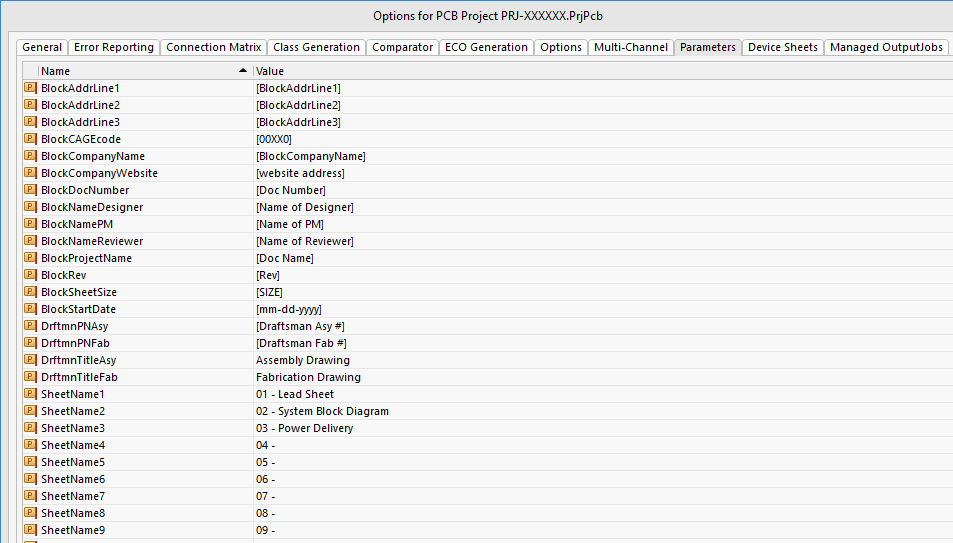
There are three prefixes used in the template:
- Block - This indicates that the information would be used in a title block or a block containing project information. These parameters are found in the schematic files, the schematic library, Outjob, and the Draftsman files in this template set.
- Drftmn - These parameters are used in the Draftsman files of the template.
- Sheet - This prefix is used to label individual schematic sheets.
Since these are project parameters, they may be used in any editor that will accept a project parameter. You may create new parameters as needed. You are encouraged to follow the method used for creating parameter names and to think about which editor or editors may use it. For example, if you made a parameter specific to the PCB layout, you may want the prefix to begin with "PCB."
Parameters may be deleted with caution since they may have been used in more than one editor. Note that the Outjob files make use of several parameters.
Many of the default values are in brackets. This is a placeholder indicating that the value needs to be changed in the .PrjPCB file.
In creating these templates, several Altium-defined parameters were used, such as DocumentName and CurrentDate. Parameters that do not have the prefixes listed above are Altium-defined parameters.
These libraries provide items that would be commonly used in each project. You are encouraged to copy these symbols (along with their corresponding footprints) into your company library.
The schematic library contains the following:
| NAME | FOOTPRINT | NOTE | IMAGE |
|
|
|
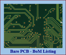
This can be placed on the schematic so that a bare PCB can be added to the bill of materials. |
 |
|
|
|
At least 2 (preferably 3) fiducials for each side of the board |
 |
|
|
|
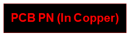
Provides the PCB part number on the top copper layer |
 |
|
|
|
Silkscreen |
 |
|
|
|
Silkscreen |
 |
|
|
|
Silkscreen |
 |
|
|
|
Title block for page 2 of the schematics and thereafter |
 |
|
|
|
Title block for page 1 | See below |
Note: the main page title block was designed to fit into the default A size sheet in Altium Designer.
Included in the template set are 11 schematic sheets. All these sheets have been formatted to a B-size sheet. There is no requirement to use these sheets, and they may be modified or deleted as necessary. No .SchDot file was used for these sheets. The lead sheet is an introductory sheet that many companies use.
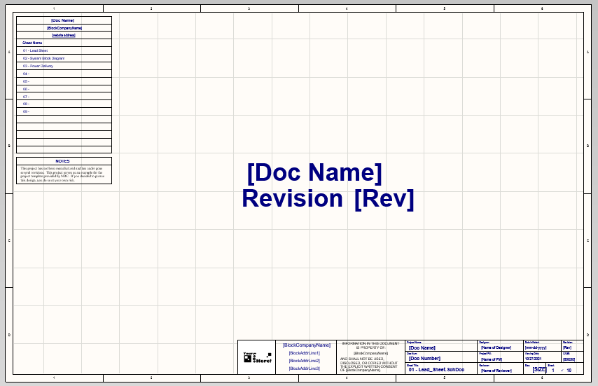
Though the title bar comes from the library, the reference list of schematic sheets and the Note were drawn directly onto the schematic. If desired, these features could also be added to the schematic library.
The Block Diagram sheet is used to provide a general picture of the design. If using a hierarchical design structure, the sheet symbols could be used on this sheet.
Except for the back page, the remaining schematic sheets will look as follows:
The back page contains all the silks and other project-related symbols.
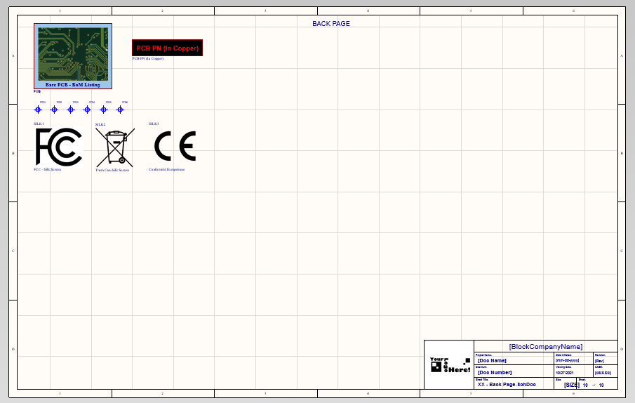
Since the schematic back page contains the bare PCB component, this will be listed in the Active BOM document. This was used to provide an example of a manually defined part choice. It follows the following format:
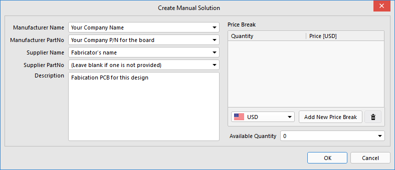
Note: attempts to use project parameters in the manual solution for the fabricated board do not work. You will have to type them in.
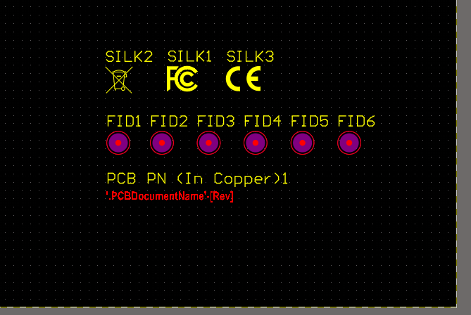
Other than the silks, fiducials, and the copper-based project name found on the back page of the schematic along with Nine Dot Connects Rev 2 mechanical stackup, no other aspects of the PCB layout were changed. Layer stack, rules, and PCB board shape are too specific to your project for this template to make recommendations.
Other than the importation of the mechanical layer stack up, no additional information was added to the mechanical layers. Fab notes, drill charts, and other mechanical-related details are found in the fabrication and assembly Draftsman documents.
Two Draftsman files have been provided, one for fabrication and the other for assembly.
All Draftsman pages provided have title blocks. Since Draftsman does not use any libraries, the title block was created in the Draftsman document. Therefore, these title blocks can be easily modified. If creating a new page in Draftsman, an existing title block will need to be copied and pasted onto the new page.
The fabrication drawing contains the following sheets:
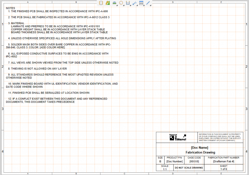
- Page one contains the fabrication notes. Please review this list and remove any line items that are not applicable. Modify as needed to the specifics of your project. If you are not sure of a line item in the example, please consult your fabricator.
- The second page contains the stack up.
- The third page is for the transmission line structure table.
- The fourth page is for the isometric view of the board. Note that the title block declares "DO NOT SCALE DRAWING." However, since Altium Designer allows for the scaling of drawings, this can be modified to your project needs.
- The fifth page is for a top side view of the board
- The sixth page contains the drill drawing view and the drill table
The assembly drawing contains the following sheets:
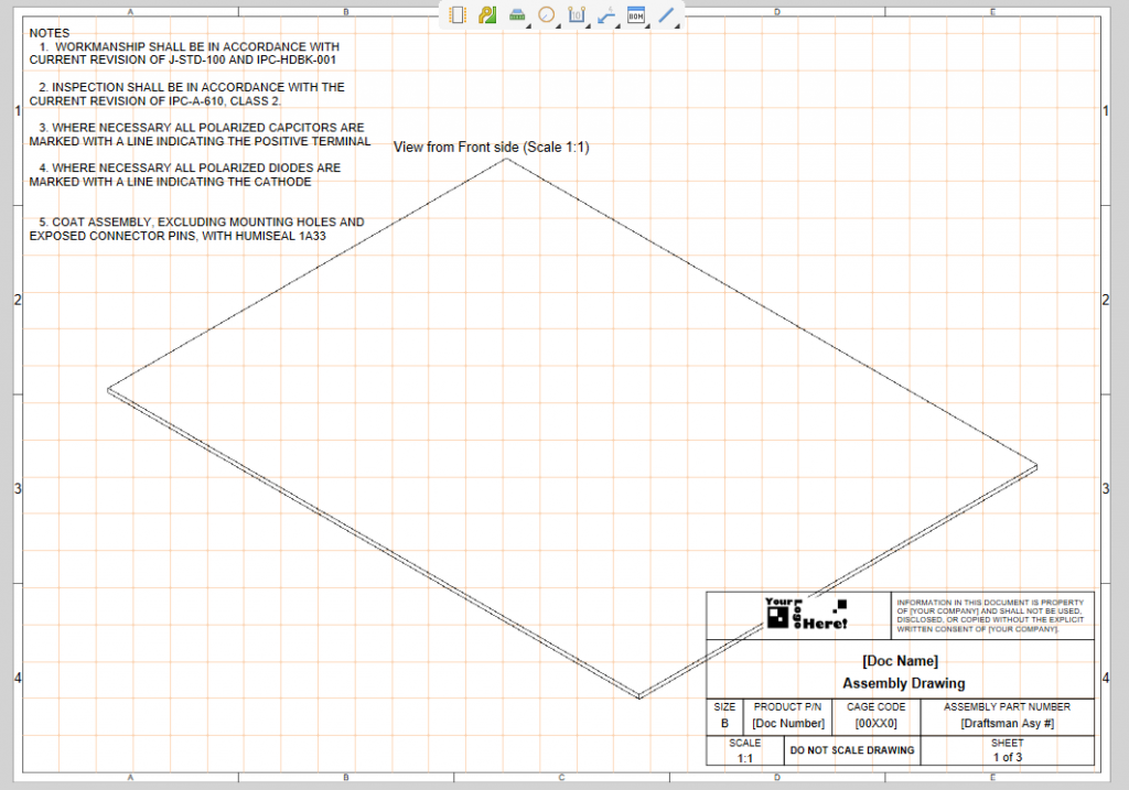
- Page one contains the assembly notes. Please review this list and remove any line items that are not applicable. Modify as needed to the specifics of your project. If you are not sure of a line item in the example, please consult your assembler. Also included is the front side view of the board
- The second page is for a top side view of the board
- The third page is for a bottom side view of the board
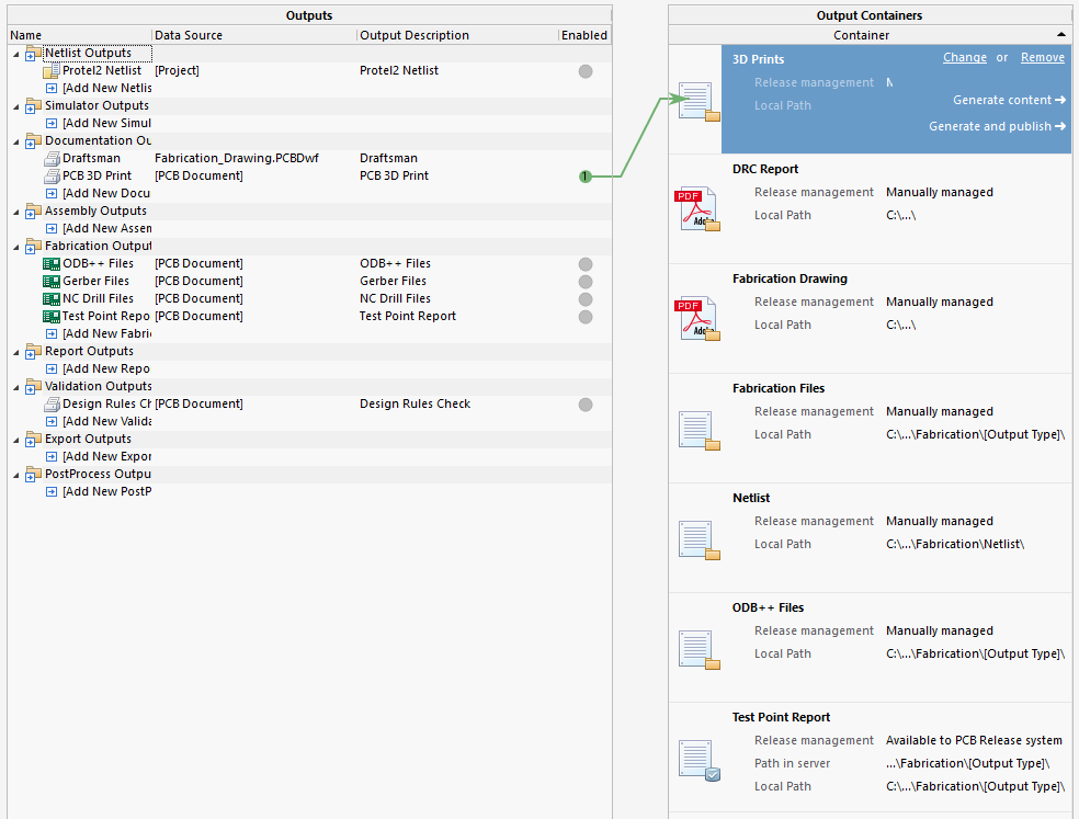
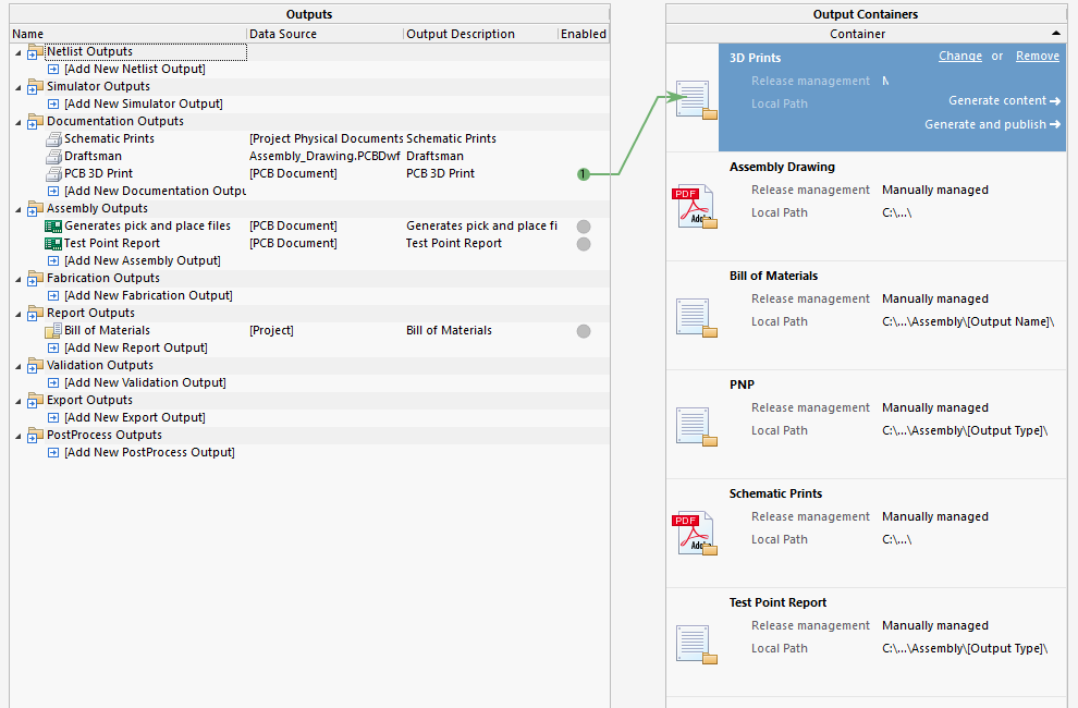
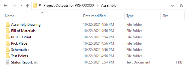
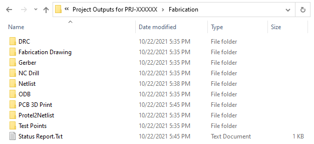
There are 2 OutJob files associated with the template set, one for fabrication and the other for assembly. In both files, the paths for the documents were set to "manually managed" and to create folders below the Project Outputs directory in the project directory.
For Fabrication:
For Assembly:
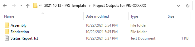
When generated, the output directories will look as follows:
This file contains the Revision 2 mechanical layer set from Nine Dot Connects. It can be imported into the footprint library (.PCBlib) or PCB layout (.PCBdoc) by using Tools >> Import Mechanical Layers in the editor menu. Note that footprint library (.PCBlib) or PCB layout (.PCBdoc) already have the mechanical layers imported.
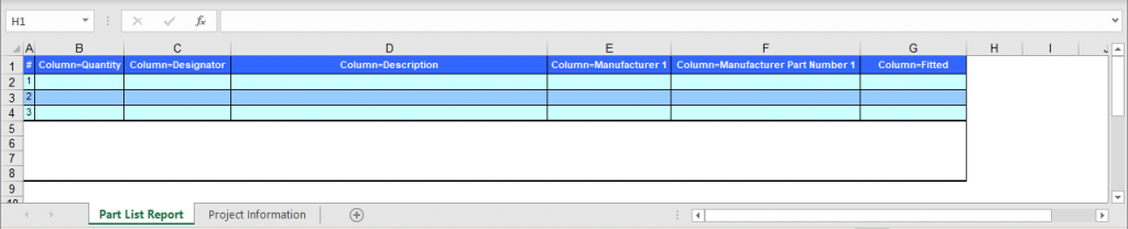
This Excel file is used by the assembly. OutJob file to format the bill of materials.
We are confident that more can be added to these files to make the template more versatile and efficient. Feedback is welcome.
| DATE | REVISION | AUTHOR | NOTES |
|
|
|
|
Initial Release |
|
|
|
|
Corrected PCB and copper paramter |
Download Template Set
Learn More

