3D Component Models
There are 3D component models, and then there are proper 3D models
It is one thing to download a 3D component; It is another to represent it to ensure that the assembly operation will not encounter issues during the placement.
In the PCB design environment, 3D models of components allow the electrical and mechanical design tools to communicate with each other. 15 years ago, this was not feasible, requiring both the electrical and mechanical designers to draw the mechanical aspect in each tool. This not only duplicated work but was also prone to error. Anything that required a tight fit between the PCB and the enclosure took much time and effort.
Fortunately, most PCB design tools allow for importing 3D models. Additionally, component manufacturers and part suppliers make their models readily available through the universal STEP format.
HOWEVER, like symbol and footprint graphics, there is no universal style guide for drawing 3D models. As a result, improper 3D models, especially connectors, can cause a respin late in the assembly process that could have been avoided.
At Nine Dot Connects, we have created numerous 3D component graphics for our customers. In the process, we have learned a few tips and tricks that we would like to impart to you.
Maximum Dimensions
One of the biggest concerns with supplier-provided models is that they rarely use the maximum tolerance value, preferring to provide the typical value. This is unfortunate since one of the main reasons for using 3D models is to perform clearance checks. Generally, it is better to use maximum dimensions to ensure proper clearance checks are performed.
NDC typically utilizes maximum dimensions when creating parts, thus ensuring the best possible representation of real-world situations.
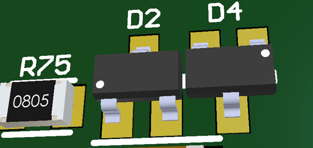
This is part of a downhole sensor board where every mil counts. Here is a layout using "typical" part dimensions.
Here is the same layout using "maximum" part dimensions, causing a possible assembly failure.
Standardization - In theory, but not in practice
Organizations like JEDIC and the IPC have recommendations for the known footprint types, such as 0402, 0602, SOICs, SOTs, etc. Unfortunately, component companies do not follow them to the letter, nor is there any enforcement body for accountability.
The "one size fits all" approach is a risky one.
To ensure proper footprints in your library, starting with a 3D model of the component you wish to use along with its datasheet to confirm that the footprint provided will work for your component is better.
Having a procedure for creating your 3D models will guide the creation of your footprints.
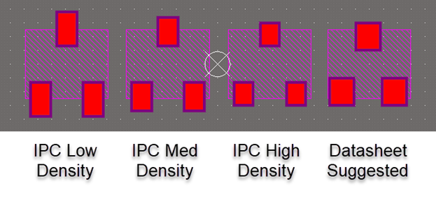
In this example, these footprints are all SOT footprints. Which is the best one to use? The one is based on the mechanical dimensions of the component you are using.
NDC recommends that the footprint and 3D match the manufacturer's datasheet. Though this creates a more extensive library, we generally find that the time it takes to create a footprint and 3D model reduces unnecessary risks of simply copying an existing one that looks similar.
Beyond Shapes
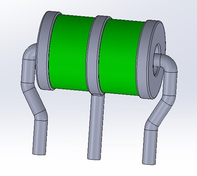
Additional characteristics can be added to enhance understanding of the component's function. For example, text can be added to a crystal or oscillator to provide frequency information. Color can be added to properly represent a particular LED, and so on.
At NDC, we have an extensive library of "starter" models that we can quickly and easily modify to fit a client-defined standard, including adding additional text or other features the client may require.
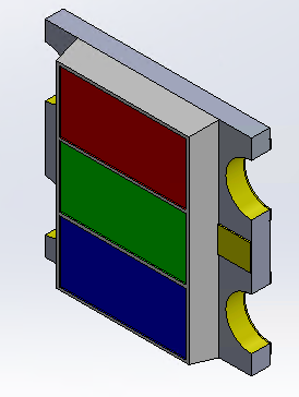
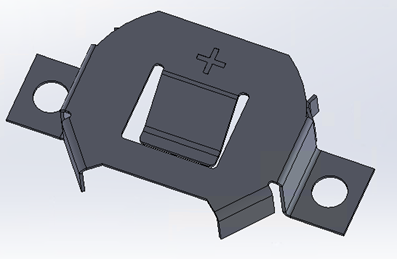
We also provide special case models for items such as tri-colored LEDs so that it is obvious what the component is when placed on the board.
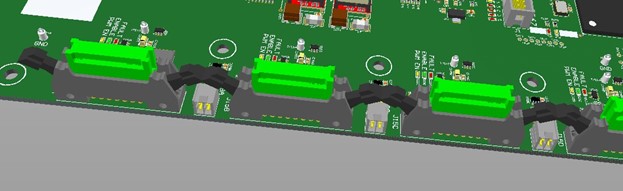
Connectors and Mating Parts
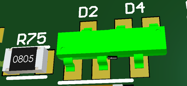
Perhaps the biggest "gotcha" that proper 3D models can help prevent is connector placement and, more importantly, the mating connector size. Many electrically functional PCBs need to be respun because of unexpected interference with the mating connector. Unfortunately, the mating connector is rarely included in supplier-provided models.
At NDC, whenever we make a connector model, we actually make 4 or more versions as needed:
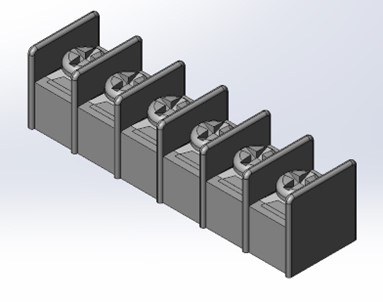
This is an example of the terminal block in which NDC added the screws to enhance the model.
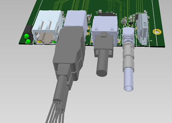
What's wrong with this picture? If the mating connector had not been added for clearance check, it would not have been detected until the assembly was complete and the designers were ready to prototype.
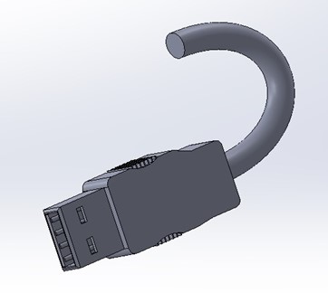
In both examples, we added the cable to the mating connector so the board designer could account for the cable in their design.
Which End is Up?
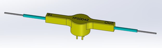
There is no universal standard for component orientation. In most cases, the component must be flipped to its proper X, Y, and Z axis and made flush to the X-Y plane. Though Altium Designer has tools to aid this process, having these orientations correct makes the component creation all the quicker.
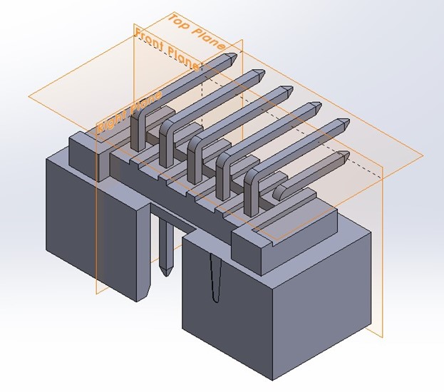
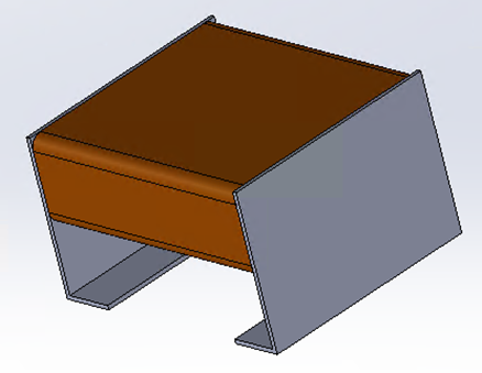
Though this was downloaded from the manufacturer, we modified the orientation so that it could be placed quickly into the footprint without any additional manipulation of the orientation.
Modifications
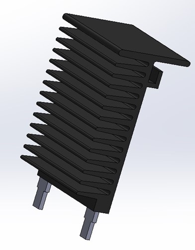
Sometimes, a component needs to be bent to be placed against a thermal pad or to reduce its height. Modifying the component to represent the 3D model in its final position is not uncommon.
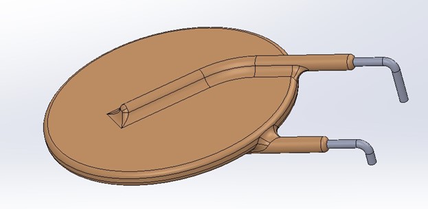
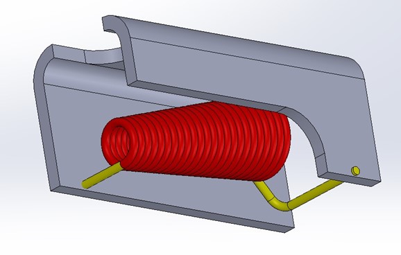
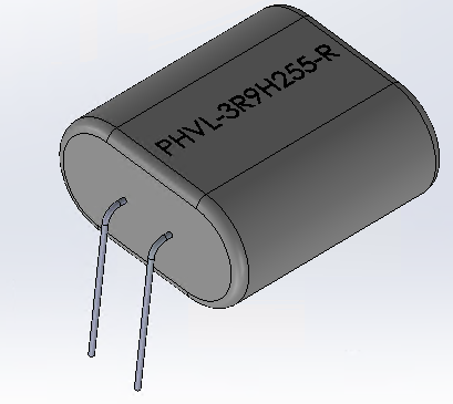
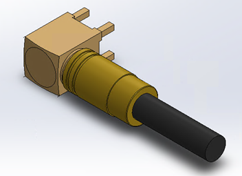
This resettable fuse was redrawn in a right-angle fashion per the customer's needs.
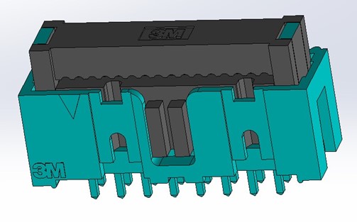
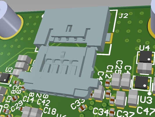
In other cases, aspects of the component need to be added or modified to ensure proper fit. For example, consider a socket that has latches to eject the plug. All too often, the same for these are missed since the latches were not in their expanded position.
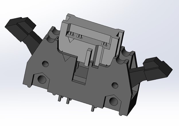
This connector was modified to insert the mating connector and expand its latches to ensure proper clearances.
Customization
Sometimes, you may have an in-house component that needs to be added to the PCB. At NDC, we can accommodate such requests like the one shown: