- Overview
- Library Service Options
- Library Clean Up
- Library Sustainment
- Librarian On-Demand
- Quote Request
- Why Conformity Matters
- Ugly Components
- Symbol Style Guide
- 3D Model Included
- Library Intro/Philosophies ⇩
- SVN (or GIT) Library
- DFM Library Example
- Library Resource Videos (18)
- Avoiding Gotchas
- Altium Vault Services
- Altium 365 and its Evolution
- Configuration Setup ⇩
- Life After Concord Pro
- Vault Management Videos (16)
- Overview
- Point of Entry
- L9 Videos (4)
- L9 vs. Vault
- Evaluation
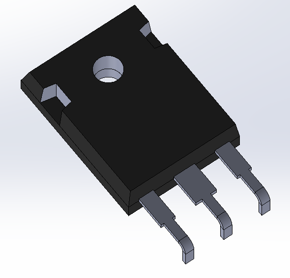
3D Is Part Of The Component Makeup
Our components include a 3D rendering if the component has one. The rare exceptions include embedded copper inductors, test points, and fiducials, all of which are defined by the copper itself. Though it makes for an excellent rendering of the PCB in the end, the purpose goes way beyond it.
We believe the component's 3D representation is as important as the symbol and footprint. The PCB is a mechatronic device. It is as much a mechanical creature as it is an electrical. In most cases, the PCB will need to be integrated into a physical device that a mechanical engineer is designing.
The ability to add 3D components to the footprint in Altium Designer was a significant step in bridging the chasm between electrical CAD and mechanical CAD tools. How so? Allow us to relate a story.
"During my time at a defense firm, I was tasked with creating a set of PCBs that could be pressed onto the pins sticking out of a backplane to aid signal testing and debug operations. Each board was to be custom to the card inserted into the backplane. Given the limited space, we had to ensure that the board dimensions were kept within their respective slots and that no components on these boards would collide with other boards or components on the backplane.
I was blessed to have been given one of the department's best mechanical engineers and PCB layout artists. There was much discussion about how we would make this work. In the end, a plan was in place, and the drawings began. However, the PCB layout and the mechanical tool were incompatible, and the idea of using a STEP file in an EDA tool had not been developed.
As a result, the mechanical information had to be drawn twice in both the EDA and mechanical tools. And sure enough, despite our best efforts, we had to respin the boards due to mismatches.
We simply grinned and bared it. We worked with what we had and got it right on the 2nd spin."
With the 3D capabilities of Altium Designer, a story of this nature should be a story of the past. When Altium introduced its 3D capabilities and the ease of adding 3D representations (a.k.a. STEP files) to the footprint, the chasm between ECAD and MCAD was practically bridged overnight. PCB 3D renderings could be handed to the mechanical team in STEP format to ensure that the board and its components fit into the designed enclosure. Further innovations have allowed the real-time graphics interchange between EDA and mechanical design tools.
But this can only happen when a 3D representation is added to the footprint. When Nine Dot Connects makes a component for a customer, a 3D model will be included because, to us, it is THAT important.